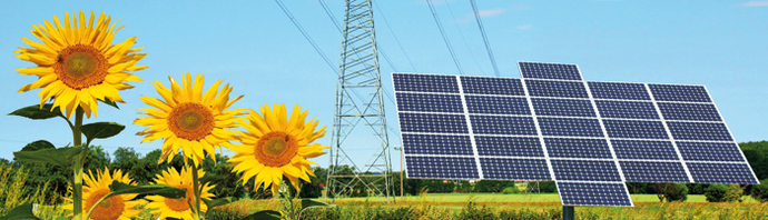
CiA® 437: CANopen application profile for grid-based photovoltaic systems
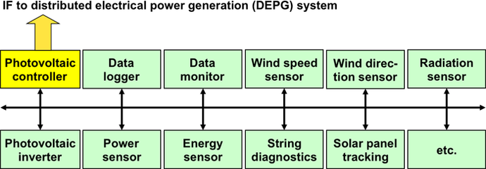
The CiA 437 application profile specifies the CANopen CC (classic) interfaces for devices in photovoltaic control systems. This includes interfaces to the photovoltaic controller, photovoltaic inverters, wind direction sensors, temperature sensors, radiation sensors, energy sensors, power sensors, solar panel tracking systems, etc. The three-part specification comprises general definitions, pre-defined communication objects, and process data specifications.
The profile defines several virtual devices. A virtual device supports a set of process data objects and is a non-divisible function, which can be located somewhere in the network. Two (or more) virtual devices can be located on the same physical CANopen CC device. In the photovoltaic system, there can be one or more instances of the same virtual device type (e.g. inverter 1, inverter 2, inverter 3), which have to own a device number. A mechanism for automatic device number assignment is proposed (not mandatory) in CiA 437-1. CiA 437-1 also gives an overview on process data objects to be implemented (mandatory, conditional, or optional) by certain virtual devices.
The photovoltaic controller is a virtual device with the NMT (network management) manager functionality and the capability of automatic device number assignment, if implemented. It also provides the SDO (service data object) client functionality to the SDO servers of other devices. This enables a peer-to-peer communication between the CANopen CC device with the photovoltaic controller functionality and other CANopen CC devices. A photovoltaic system may consist of more networked devices than 127 (node-ID limit in one CANopen CC network), requiring interconnection between several CANopen CC networks. Transfer of data between the networks is possible using remote emergency and remote SDO functional elements (see CiA 302-7). Hereby, the photovoltaic controller acts as the system manager. It also optionally provides an interface to other distributed electrical power generation systems (e.g. wind-craft, diesel, biogas, etc.) and optionally links the photovoltaic system to the electrical power distribution control system.
Each photovoltaic inverter (up to 254 possible) implements a TPDO (transmit process data object) providing the 64-bit inverter’s total output energy value. The photovoltaic controller as well as the data monitoring/logging device can collect these data. Each physical CANopen CC device implements one MPDO (multiplexed process data object) to be transmitted in broadcast and up to 127 MPDOs to be received. Thus, each CANopen CC device is able to exchange its implemented process data objects in a broadcast manner i.e. to each other “interested” device in the photovoltaic plant. To be transmittable via MPDO, all process data parameters (except inverter’s total output energy) were defined as values smaller or equal to 32 bit.
The process data and parameters (see CiA 437-3) for inverters include all required electrical values (current, voltage, power, frequency, energy), temperatures, statuses and commands, test types, as well as diverse limits for failure-free inverter functioning (e.g. operating, disconnection, reconnection). For sun tracking systems the geometry, technology, location longitude and latitude, as well as statuses and commands (also for drives and motors) are specified. Parameters for control (actual and target values, offsets, intervals), the azimuth and elevation, as well as for reaction on special conditions (storm, snow drop, maintenance, night) are given as well. In addition, the process data for a string diagnostic device and a grid diagnostic device is specified in detail. The simpler devices with less process data are, for example, temperature sensors, radiation sensor, energy sensor, wind sensor, as well as generic digital and analog I/Os.
CiA 437-compliant devices support a bit-rate of 125 kbit/s (and optionally others) and one of the four connectors (RJ45, 5-pin M12, D-SUB 9-pin, open-style connector) with the pinning as recommended in CiA 106. The physical layer definitions follow those as specified in CiA 301. For node-ID assignment and bit-rate reconfiguration it is recommended to use the CANopen CC layer setting services (see CiA 305). Support of the emergency message and the heartbeat functionality is mandatory.
| Title | Details | Status Size |
Published Action |
|---|---|---|---|
| CiA 437-1 version 1.1.0CANopen application profile for grid-based photovoltaic systems - Part 1: General definitions | DescriptionThis document specifies the CAN-related physical layer, the general system architecture, and some common CiA 301 communication parameter objects. It also defines, which process data and parameters are used by the virtual devices specified for grid-based photovoltaic systems Keywordsn/a | DSP784 KiB | 2024-01-09Login |
| CiA 437-2 version 1.1.0CANopen application profile for grid-based photovoltaic systems - Part 2: Pre-defined communication objects | DescriptionThis document specifies default communication objects and general communication
parameters for CANopen devices in grid-based photovoltaic systems. Keywordsn/a | DSP305 KiB | 2024-01-09Login |
| CiA 437-3 version 2.0.1CANopen application profile for grid-based photovoltaic systems - Part 3: Profile data objects | DescriptionThis document specifies in detail the process data and parameters of the virtual devices defined for use in grid-based photovoltaic systems. Keywordsn/a | DSP4.0 MiB | 2024-02-27Login |
| CiA 301 version 4.2.0CANopen application layer and communication profile | DescriptionThis specification specifies the CANopen application layer. This includes the data types, encoding rules and object dictionary objects as well as the CANopen communication services and protocols. In addition, this specification specifies the CANopen network management services and protocols. This specification specifies the CANopen communication profile, e.g. the physical layer, the predefined communication object identifier connection set, and the content of the Emergency, Timestamp, and Sync communication objects. Keywordsn/a | PAS3.0 MiB | 2011-02-21Login |
| CiA 305 version 3.0.0CANopen layer setting services (LSS) and protocols | DescriptionThis document specifies the layer setting services (LSS) and protocols for CANopen. These services and protocols are used to inquire or to change the settings of three parameters of the physical layer, data link layer, and application layer on a CANopen device with LSS server capability by a CANopen device with LSS manager capability via the CAN network. Keywordsn/a | DSP1.9 MiB | 2013-05-08Login |
| CiA 106 version 1.1.0Connector pin-assignment recommendations | DescriptionThis document recommends the connector pin-assignment for CAN interfaces. This includes the CAN_H and CAN_L pins, the ground pin, and the power supply pins. Keywordsn/a | TR0.9 MiB | 2023-07-11Login |