CiA® 1305: Layer setting services (LSS) for CANopen FD
LSS introduces communication services between an LSS manager (typically residing in the host controller) and LSS servers. LSS enables the LSS manager to modify the LSS server’s CANopen FD network-ID and node-ID. Additionally LSS provides means to modify the CAN FD bit timing parameters (for nominal bit-rate and data bit-rate) in all CANopen FD devices. The LSS for CANopen FD are specified in the document CiA 1305.
CANopen FD network-ID and node-ID assignment via LSS
The entire 128 bit of the CANopen FD Identity object 1018h (vendor-ID, product-code, revision number, serial number, as specified in CiA 1301) are considered as LSS address. The LSS address is a unique number, for any CANopen FD device. Therefore an LSS manager can differentiate between several LSS servers, by means of the LSS address, even if these LSS servers do not own a valid network-ID or node-ID. Via the LSS switch state selective FD command, the LSS manager forces exactly one LSS server to enter the LSS configuration state. Only in this state the LSS server accepts a new network-ID or node-ID that is proposed by the LSS manager. It is the LSS manager’s task to ensure that during the assignment of the network-ID or node-ID, there is only one LSS server in the LSS configuration state.
In case the LSS addresses of the LSS servers are unknown to the LSS manager, the LSS manager may have several means to detect the LSS server's LSS addresses. In case the LSS servers own already a valid network-ID and node-ID, the LSS manager just reads the content of the object 1018h, of all LSS servers in the system, via USDO (universal service data object). In case the LSS servers do not own a valid network-ID and node-ID the LSS manager has to rely on additional LSS services. The LSS switch state selective FD service enables the LSS manager to scan via 4-bit-nibble-masks, whether there exists an unconfigured LSS server, that's LSS address is in a given LSS address range. By executing several scanning cycles, the LSS manager can identify exactly one unconfigured LSS server and can provide subsequently a valid CANopen FD network-ID and node-ID.
CANopen FD bit timing parameter modification, via LSS
The LSS enable the LSS manager to switch the entire CANopen FD network from one pair of nominal bit-rate and data bit-rate, to another. Changing the bit timing parameters in all CANopen FD devices, connected to the very same CANopen FD network, causes this. The LSS manager configures via LSS in all CANopen FD devices in the network the intended bit timing parameters, individually. After the successful configuration, the LSS manager requests the bit timing switch, by means of a global LSS service, at all LSS servers, at the very same time. After a switch delay, all devices in the CANopen FD network operate on the new nominal bit-rate and data bit-rate, based on new bit timing parameters.
It is recommended to use the switching of LSS bit timing parameters very carefully. In case there is at least one device that is not switching correctly, the CANopen FD network shows a severe error behavior. A proper control system is not available any longer. CAN controllers of CANopen FD devices, operating on the “wrong” bit timing, end up in the CAN error state Bus off, cannot communicate via CAN any longer, and have to be dismantled from the system for re-configuration purposes. Only in a separate system, running on the same bit-rates, these devices can be re-configured, prior to install them again in the control system. For the initial adjustment of the CANopen FD bit timing parameters, the LSS bit timing switch service is not suitable. For such scenarios, methods such as the CANopen automatic bit-rate detection (CiA 801) may be used, in an adapted format, suitable for CANopen FD.
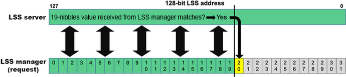
Identification of unconfigured LSS servers using LSS switch state selective FD service
In case several unconfigured LSS servers exist in a CANopen FD system, they can be identified by means of the LSS switch state selective FD service. To fulfill the service, the 128-bit LSS address was divided into 32 pieces (nibbles) of four bit each. The LSS manager consequently asks the LSS servers for the values of each nibble. 16 messages with the CAN-IDs from 07D0h to 07DFh are used as possible feedback. When the LSS manager requests the value of the first nibble, the LSS servers reply with 07D0h if their first nibble is zero, 07D1h if it is one and so forth until 07DFh if their first nibble is 0Fh. Then, the LSS manager takes the first response (all others are ignored for this cycle) and packs the first nibble value into the next request. The LSS servers with the first matching nibble inform the LSS manager about the second-nibble value using the 16 messages with the mentioned CAN-IDs. This cycle is repeated until all nibbles have been processed and a single, unconfigured LSS server is identified. Then, the LSS manager can assign the network-ID and the node-ID to this LSS server.
To decrease the boot-up time in CANopen FD systems that may be modified by the end user, the LSS manager could store LSS addresses that have been identified. On each power-up, the LSS manager could try those LSS addresses first and if there is then still an unconfigured LSS server left in the system, the LSS switch state selective FD cycle is started.
| Title | Details | Status Size |
Published Action |
|---|---|---|---|
| CiA 1305 version 1.0.0CANopen FD layer setting services (LSS) and protocols | DescriptionThis document specifies the layer setting services (LSS) and the layer setting protocols for CANopen FD devices. Keywordsn/a | DSP1.0 MiB | 2022-05-11Login |
| CiA 1305 version 1.0.6CANopen FD layer setting services (LSS) and protocols | Descriptionn/a Keywordsn/a | WD1.2 MiB | 2023-12-11Login |